Cisco Config
Vlan
Day 16
- A LAN is a single broadcast domain, including all devices in that broadcast domain
- A broadcast domain is the group of devices which will receive a broadcast frame (destination MAC ffff.ffff.ffff) send by any one of the members.
Basic Configuration
Assign Ports to VLANs: Associate switch ports with their respective VLANs (replace interface_id and vlan_id):
1
2
3
switch(config)# interface interface_id or range
switch(config-if)# switchport mode access
switch(config-if)# switchport access vlan vlan_id
Name VLANs: Assign names to VLANs for easier identification (replace vlan_id and vlan_name accordingly):
1
2
switch(config)# vlan vlan_id
switch(config-vlan)# name vlan_name
Verify Configuration: Use the show vlan brief command to confirm the configured VLANs and their respective port assignments.
1
switch(config-vlan)# show vlan brief
- If you assign a switch interface to a VLAN that doesn’t exist yet, the switch will create the VLAN automatically.
- An access port is a switchport which belong to a single VLAN,and usually connects to end hosts like PCs.
- Switchports which carry multiple VLANs are called ‘trunk ports’
example;
1
2
3
4
5
6
7
8
9
10
11
12
13
14
15
16
17
18
switch(config)# interface range fastEthernet 0/1 - 5
switch(config-if-range)# switchport mode access
switch(config-if-range)# switchport access vlan 10
switch(config-if-range)# exit

switch(config)# interface range fastEthernet 0/6 - 10
switch(config-if-range)# switchport mode access
switch(config-if-range)# switchport access vlan 20
switch(config-if-range)# exit

switch(config)# vlan 10
switch(config-vlan)# name vlan_name
switch(config-vlan)#exit

switch(config)# vlan 10
switch(config-vlan)# name vlan_name
switch(config-vlan)#exit
Day 17
Switches will ‘tag’ all frames that they send over a trunk link. This allows the receiving switch to know which VLAN the frame belongs to
1
2
 "tagged port = trunk port"
 "access port = untagged port"
- There are two main trunking protocols: ISL (Inter-Switch Link) and IEEE 802.1Q.
- We call 802.1Q ‘dot1q’.
- ISL is an old Cisco proprietary protocol, created before the industry standard IEEE
- 802.1Q. Dot1q is an industry standard protocol created by the IEEE (Institute of Electrical and Electronics Engineers)
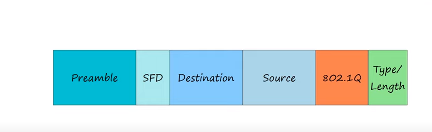
- The dot1q tag is inserted between the source MAC address and the type/length fields of the Ethernet header.
Trunk Configuration
1
2
3
switch(config)# int g0/0
switch(config-if)# switchport trunk encapsulation dot1q
switch(config-if)# switchport mode trunk
- use the
show interfaces trunkcommand to confirm
1
switch# show interfaces trunk
Modifying allowed VLANs (add/remove/all/except/none)
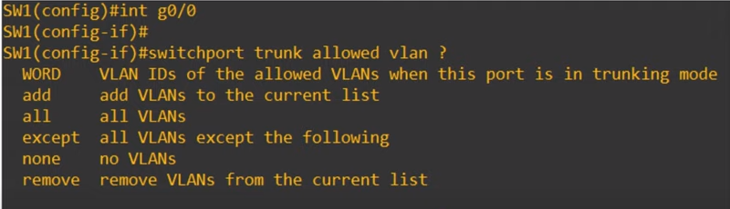
**WORD** allows you to simply configure the list of VLANs allowed.
1
2
switch(config)# interface GigabitEthernet 0/0
switch(config-if)# switchport trunk allowed vlan 10,3
- ADD allows you to add allowed VLANs to the currently existing list. Currently VLANs 10 and 30 are allowed,
1
switch(config-if)# switchport trunk allowed vlan add 20
- remove allows you to removed vlan from the list of allowed VLANs
1
switch(config-if)# switchport trunk allowed vlan remove 20
NONE no VLANs are allowed on the trunk
1
2

switch(config-if)# switchport trunk allowed vlan none
EXCEPT allows all VLANs except the ones you specify
1
2

switch(config-if)# switchport trunk allowed vlan except 20,30
Native VLAN Configuration
- change the native VLAN on a trunk port
1
2
switch(config-if)# switchport trunk native vlan <VLAN number>
#for security purposes, it is best to change the native VLAN to an unused VLAN
Configuring SW01 interface g0/0 as a trunk port
1
2
3
4
5
SW02(config)# int g0/0
SW02(config-if)# switchport trunk encapsulation dot1q
SW02(config-if)# switchport mode trunk
SW02(config-if)# switchport trunk allowed vlan 10,30
SW02(config-if)# switchport trunk native vlan 1011
Configuring SW02 interface g0/0 as a trunk port
1
2
3
4
5
SW02(config)# int g0/0
SW02(config-if)# switchport trunk encapsulation dot1q
SW02(config-if)# switchport mode trunk
SW02(config-if)# switchport trunk allowed vlan 10,30
SW02(config-if)# switchport trunk native vlan 1011
Configuring SW02 interface g0/1 as a trunk port
1
2
3
4
5
switch(config)# int G0/1
switch(config-if)# switchport trunk encapsulation dot1q
switch(config-if)# switchport mode trunk
switch(config-if)# switchport trunk allowed vlan 10,20,30
switch(config-if)# switchport trunk native vlan 1011
1
SW02(config)# vlan 30
Router on a Stick (ROAS)
It’s the name used for this method of inter-VLAN routing
- Create three sub-interfaces on a single physical interface to enable inter-VLAN routing. This allows routing between three VLANs using a single physical interface.”
1
2
3
G0/0.10 for VLAN10,
G0/0.20 for VLAN20,
G0/0.30 for VLAN30.
- These three logical sub-interfaces are really one physical interface,but they can operate like three separate interfaces.
Configuring R01 interface g0/0
1
2
3
4
5
6
7
8
9
10
11
12
13
14
R01(config)# interface g0/0
R01(config-if)# no shutdown

R01(config)# interface g0/0.10
R01(config-subif)# encapsulation dot1q 10
R01(config-subif)# ip address 192.168.1.1 255.255.255.0

R01(config)# interface g0/0.20
R01(config-subif)# encapsulation dot1q 20
R01(config-subif)# ip address 192.168.2.1 255.255.255.0

R01(config)# interface g0/0.30
R01(config-subif)# encapsulation dot1q 30
R01(config-subif)# ip address 192.168.3.1 255.255.255.0
- ROAS is used to route between multiple VLANs using a single interface on the router and switch.
- The switch interface is configured as a regular trunk.
- The router interface is configured using subinterfaces. You configure the VLAN tag and IP address on each subinterface.
- The router will behave as if frames arriving with a certain VLAN tag have arrived on the subinterface configured with that VLAN tag.
- The router will tag frames sent out of each subinterface with the VLAN tag configured on the subinterface
Configuring Native VLAN on a Router
There are 2 methods of configuring the native VLAN on a router
- Use the command
encapsulation dot1q vlan-id nativeon the router subinterface
This tells the router that this subinterface belongs to the native VLAN, and it will function just like the native VLAN on a switch. It will assume untagged frame belong to the native VLAN, and frames sent in the native VLAN will not be tagged
- The second option is to not use a subinterface at all, but just configure the IP address for the native VLAN on the physical interface of the router. The
ENCAPSULATION DOT1Qcommand is not necessary in this case.
Inter-VLAN Routing via SVI (Switch Virtual Interface)
Spanning Tree Protocol
- STP is an industry standard protocol IEEE 802.1D,
- Switches from ALL vendors run STP by default
- STP prevents Layer 2 loops by placing redundant ports in a blocking state, essentially disabling the interface
- These interfaces act as backups that can enter a forwarding state if an active interface fails.
- Interfaces in a forwarding state behave normally. They send and receive all normal traffic
Interfaces in a blocking state only send or receive STP messages (called BPDUs,or Bridge Protocol Data Units)
- By selecting which ports are forwarding and which ports are blocking, STP creates a single path to and from each point in the network. This prevents Layer 2 loops.
- There is a set process that STP uses to determine which ports should be forwarding and which should be blocking.
- STP-enabled switches send/reveive Hello BPDUs out of all interfaces, the default timer is 2 seconds the switch will send a Hello BPDU out of every interface, once every 2 seconds.
If a switch receives a Hello BPDU on an interface, it knows that interface is connected to another switch
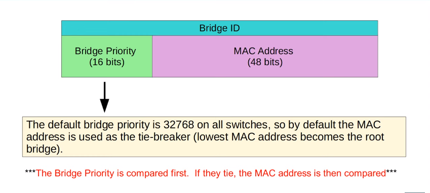
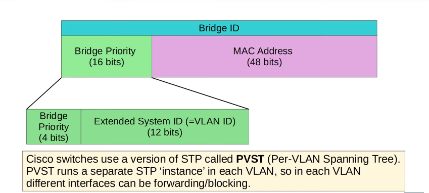
- Switches use one field in the STP BPDU, the Bridge ID field, to elect a root bridge for the network
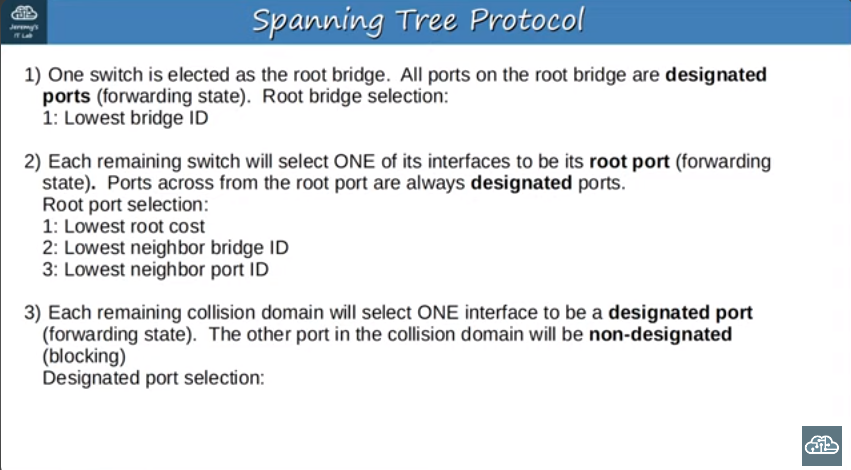
- The switch with the lowest Bridge ID becomes the root bridge.
- ALL ports on the root bridge are put in a forwarding state, and other switches in the topology must have a path to reach the root bridge.
EtherChannel
EtherChannel Load-Balancing Verification and Configuration
Verification:
- Use
SHOW ETHERCHANNEL LOAD-BALANCEto check the current load-balancing method.
1
show etherchannel load-balance
Configuration:
- Use
PORT-CHANNEL LOAD-BALANCE** <METHOD>**followed by the desired method.
1
2
port-channel load-balance [method]
port-channel load-balance src-dst-mac
- Cisco switches typically provide several load-balancing methods for EtherChannel. The available load-balancing methods include:
- Src-dst-ip: Load balancing based on source and destination IP addresses.
- Src-dst-mac: Load balancing based on source and destination MAC addresses.
- Src-dst-port: Load balancing based on source and destination port numbers.
- Src-ip: Load balancing based on source IP address only.
- Src-mac: Load balancing based on source MAC address only.
- Src-port: Load balancing based on source port number only.
- Dst-ip: Load balancing based on destination IP address only.
- Dst-mac: Load balancing based on destination MAC address only.
- Dst-port: Load balancing based on destination port number only.
- Adaptive: Load balancing based on a combination of factors, adapting to the flow characteristics.
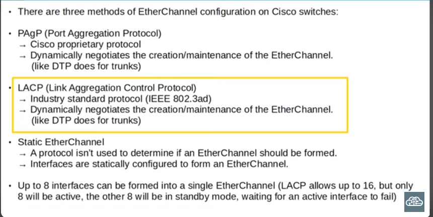
EtherChannel protocols - PAgP, LACP, Static
EtherChannel Configuration - PAgP
Use channel-group <number> mode <mode> command.
Options for <mode>
desirableorautofor PAgP.
1
2
interface range g0/0 - 3
channel-group 1 mode desirable
- If both sides of the connection are set to auto, no etherchannel will be formed.However, auto and desirable, or desirable and desirable, will form an etherchannel.
EtherChannel Configuration - LACP
Use channel-group <number> mode <mode> command.
Options for <mode>
• active or passive for LACP
1
2
interface range g0/0 - 3
channel-group 1 mode **active**
- LACP uses passive mode. So, if both ends are configured in passive mode an EtherChannel won’t be formed.However, active and passive, or active and active, will form an EtherChannel.
EtherChannel Configuration - Static
Use channel-group <number> mode on command
- on mode only works with on mode. On and desirable, or on and active will not successfully form an EtherChannel.
- The
CHANNEL-PROTOCOLcommand allows manual configuration of the EtherChannel negotiation protocol. - Syntax:
CHANNEL-PROTOCOL {LACP | PAGP} - Normally, this command is not widely used, as the negotiation protocol is automatically determined based on the
CHANNEL-GROUPmode.
Automatic Protocol Determination
- When configuring EtherChannel using
CHANNEL-GROUP, the negotiation protocol is automatically chosen:CHANNEL-GROUP 1 MODE DESIRABLEorAUTO: Automatically uses PAgP.CHANNEL-GROUP 1 MODE ACTIVEorPASSIVE: Automatically uses LACP.
Configuring Port-Channel Interface after EtherChannel Setup
- After successfully configuring the EtherChannel, regardless of the chosen mode (PAgP, LACP, or static), the next step is to configure the associated port-channel interface. In this example, I’m using LACP, but the process remains consistent across methods. The configurations were replicated on DSW1, ensuring a functional EtherChannel
Port-Channel Interface Configuration
- Enter Port-Channel Interface Mode:
Access the port-channel interface for configuration.
1
  DSW1(config)# interface port-channel 1
- Configure as Trunk:
Set the port-channel interface to operate as a trunk.
1
  DSW1(config-if)# switchport mode trunk
- Verification:
Confirm the trunk configuration by checking the output of
SHOW INTERFACES TRUNK.1
DSW1# SHOW INTERFACES TRUNK
Port-channel 1 (Po1) should be listed as a trunk.
- Consistent Configuration Across Member Interfaces:
- Member interfaces within the EtherChannel must have matching configurations.
- Ensure consistency in duplex settings, speed, switchport mode, and VLAN configurations for trunk interfaces.
- Mismatched configurations can lead to exclusion from the EtherChannel.
EtherChannel Verification with
SHOW ETHERCHANNEL SUMMARY1
SW1# SHOW ETHERCHANNEL SUMMARY
### Layer 3 EtherChannel Configuration
- Transform member interfaces to Layer 3 routed ports using
NO SWITCHPORT.
1
2
3
  interface range G0/1 - 4
  no switchport
  channel-group 1 mode active
- since we’re making a Layer 3 etherchannel, we need an IP address.
- Configure the IP address on the port-channel interface
1
2
  interface port-channel 1
  ip address [your_ip_address] [subnet_mask]
- Check the EtherChannel summary to confirm the configuration.
1
  show etherchannel summary
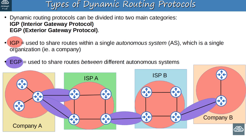
## Dynamic Routing
Network route/Host route
Network Routes
- Network routes are routes to a network or subnet.
- They are represented by a route with a mask length less than /32.
- For example, 10.0.12.0/30 and 10.0.13.0/30 are network routes.
Host Routes
- Host routes are routes to a specific host, a single address.
- They are represented by a route with a /32 mask.
Examples: 10.0.12.1/32 and 10.0.13.1/32.
- • Host routes like 10.0.12.1/32 and 10.0.13.1/32 are automatically added.
- • Network routes are for entire subnets, e.g., 192.168.4.0/24.
- • Host routes are for single addresses, specified with a /32 mask.
1
2
3
4
5
6
7
8
9
10
11
12
13
14
15
16
17
18
19
20
21
22
23
Gateway of last resort is 192.168.1.1 to network 0.0.0.0

     10.0.12.0/30 is subnetted, 1 subnets
C       10.0.12.0 is directly connected, GigabitEthernet0/0
     10.0.13.0/30 is subnetted, 1 subnets
C       10.0.13.0 is directly connected, GigabitEthernet1/0
     192.168.4.0/24 is variably subnetted, 1 subnets, 1 masks
C       192.168.4.0/24 is directly connected, FastEthernet0/1
     192.168.1.0/24 is variably subnetted, 1 subnets, 1 masks
S       192.168.1.0/24 [1/0] via 10.0.12.1
S       192.168.1.0/24 [1/0] via 10.0.13.1

# Explanation

## Network Routes
- **`10.0.12.0/30` and `10.0.13.0/30`:** These are network routes. The 'C' next to them indicates that they are directly connected. These routes represent subnets and are examples of network routes.

## Host Routes
- **`192.168.4.0/24`:** This is another network route. The 'C' indicates that it is directly connected. It's a route to the entire subnet 192.168.4.0/24.
- **`192.168.1.0/24`:** This is a summary route, and 'S' indicates that it is a static route. This could be considered a network route pointing to a whole subnet.
- **`192.168.1.0/24 via 10.0.12.1` and `192.168.1.0/24 via 10.0.13.1`:** These are host routes. The '/32' (or 255.255.255.255) indicates a specific host route. These are static routes pointing to specific hosts via the next-hop addresses.

Understanding the output of `show ip route` helps network administrators analyze how routing decisions are being made on the Cisco router.
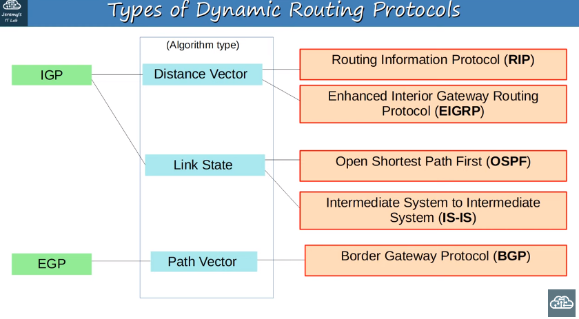
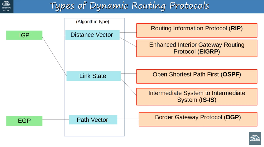
Dynamic routing protocol types
IGP/EGP algorithm types
IGP Metric chart
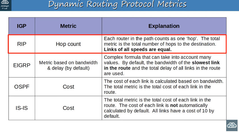
- The metric is a crucial factor in determining the best route to a destination in a router’s route table. When a router using a dynamic routing protocol learns multiple routes to the same destination, the metric is used to decide which route is the “best.” Here are key points about metrics:
- The metric value is used to evaluate the desirability of a route. Lower metric values are considered better.
- Equal Cost Multipath (ECMP):
- If a router learns multiple routes to the same destination through the same routing protocol with the same metric, both routes are added to the routing table.
- This results in load-balancing, and traffic is distributed over both routes.
Administrative Distance (AD)
is a crucial concept in routing protocols, especially when a router learns multiple routes to the same destination via different protocols. Here are the key points about Administrative Distance:
- Role of Administrative Distance:
- When a router learns routes to the same destination through different routing protocols, it uses AD to determine the preferred protocol.
- Lower AD values indicate a more trustworthy or preferred routing protocol.
- Comparison of Metrics:
- Different routing protocols use different metrics, making it challenging to directly compare routes based on metric values.
- Example: OSPF might have a metric of 30 for a route, while EIGRP might have a metric of 33280. The metrics are protocol-specific and cannot be compared directly.
- Preference Based on AD:
- The router selects the routing protocol with the lower AD as the preferred one for a specific destination.
- A lower AD suggests a higher trustworthiness of the routing protocol.
- Common Administrative Distances:
- Memorization is essential for exam preparation. Here are some common AD values used on Cisco devices:
- Directly connected networks: AD 0 (most preferred).
- Static routes: AD 1.
- External BGP (eBGP) routes: AD 20.
- EIGRP routes: AD 90.
- IGRP routes: AD 100.
- OSPF routes: AD 110.
- IS-IS routes: AD 115.
- RIP routes: AD 120.
- EIGRP external routes: AD 170.
- Internal BGP (iBGP) routes: AD 200.
- Routes with AD 255 are considered unusable.
Summary of Administrative Distance Configuration and Floating Static Routes:
In networking, you have the flexibility to configure Administrative Distance (AD) for routing protocols and static routes to influence route preference. Here’s a summary of this concept, as explained in the provided content:
- Changing Administrative Distance:
- Administrative Distance is a value assigned to routing protocols and routes to determine their trustworthiness.
- You can change the AD to influence route selection, making a less preferred route more favorable.
- Configuration of Static Route AD:
- The video demonstrates the configuration of a static route with a modified AD.
- The standard command for configuring a static route is
IP ROUTEfollowed by the destination, subnet mask, and next-hop address. - By using the question mark (
?) to check for additional options, you can find the ‘distance metric’ parameter, which allows you to set the Administrative Distance.
- Example Configuration:
- In the example, a static route is configured with an AD of 100 using the
distance metricparameter. - The command might look like:
IP ROUTE 192.168.1.0 255.255.255.0 10.0.0.1 distance metric 100.
- In the example, a static route is configured with an AD of 100 using the
- Purpose of Changing AD for Static Route:
- Modifying the AD of a static route allows you to control its preference in comparison to dynamically learned routes.
- This can be useful in scenarios where you want to create a backup or “floating” route that becomes active only when the primary route fails.
- Floating Static Routes:
- The concept of floating static routes involves configuring a static route with a higher AD than the normal default.
- This higher AD makes the static route less preferred under normal circumstances.
- If the primary route (learned dynamically) fails, the floating static route becomes active, serving as a backup.
- Use Cases:
- Changing the AD of static routes is beneficial for implementing backup routes or adjusting routing preferences based on network conditions.
- It provides a way to control the failover behavior in the event of primary route failures.
Understanding and applying changes to the Administrative Distance of static routes offer network administrators more control over route selection and improve network reliability through the use of floating static routes.
## RIP Configuration
1
2
3
4
5
  Router(config)# router rip
  Router(config-router)# version 2
  Router(config-router)# no auto-summary
  Router(config-router)# network 10.0.0.0
Enter Router RIP Configuration Mode:
1
 Router(config)# router rip
- Enters the RIP configuration mode where you can configure RIP-specific parameters.
Specify RIP Version (Use Version 2):
1
 Router(config-router)# version 2
- Sets the RIP routing process to use RIP version 2. This version is preferred over version 1 due to its support for classless routing.
Disable Auto-Summary:
1
 Router(config-router)# no auto-summary
- Disables automatic summarization of network routes. This is important for supporting Variable Length Subnet Masking (VLSM) and Classless Inter-Domain Routing (CIDR).
Activate RIP on an Interface using the Network Command:
1
 Router(config-router)# network 10.0.0.0
- Activates RIP on the specified network. In this example, RIP will be enabled on all interfaces that fall within the 10.0.0.0 network. Note that RIP uses a classful network approach.
- Memorization is essential for exam preparation. Here are some common AD values used on Cisco devices:
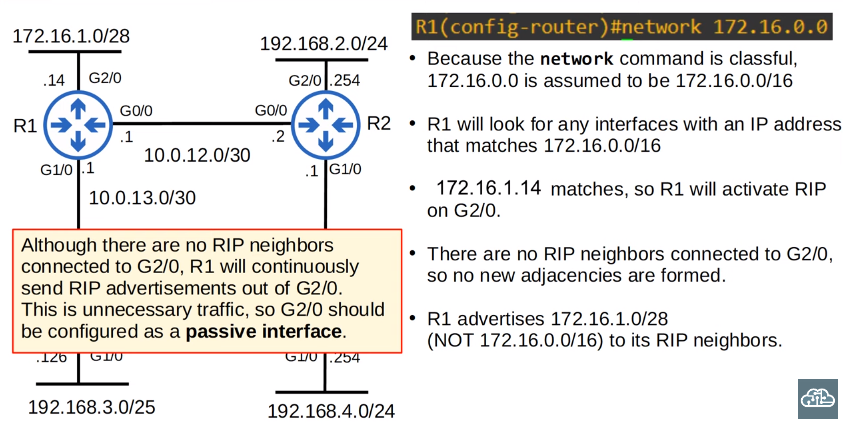
The network command command tells the router to;
- look for interfaces with an ip address that is in the specified range
- active rip on the interfaces that fall in the range
- form adjacencies with connected rip neighbors
- advertise the network prefix of the interface (not the prefix the network command)

1
2
3
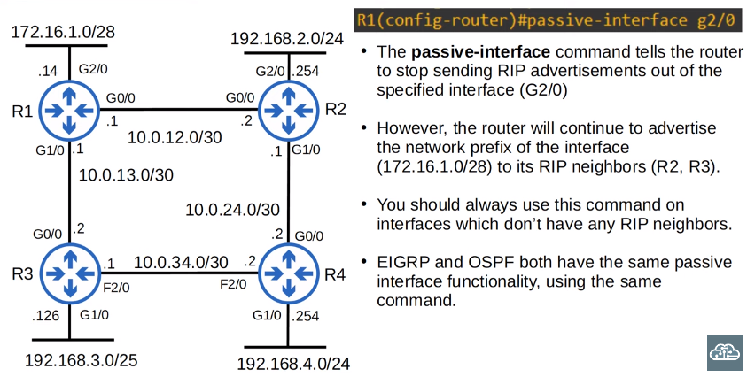
Although there are no RIP neighbors connected to G2/0, R1 will continuously send RIP advertisements out of G2/0. This is unnecessary traffic, so G2/0 should be configured as a passive interface.
passive-interface g2/0
Advertise default route via RIP
1
Router(config)# ip route 0.0.0.0 0.0.0.0 203.0.113.2
route pointing to the Internet. So, any packets that don’t match any of the other entries in R1’s routing table
The command to share this default route into RIP is DEFAULT-INFORMATION ORIGINATE,the command is done from RIP configuration mode. Now that I have entered this command, R1 will advertise the route to R2 and R3, and they
will then advertise it to R4.
EIGRP Configuration
1
2
3
4
5
Router(config)# router eigrp 1
Router(config-router)# no auto-summary
Router(config-router)#passive-interface g2/0
Router(config-router)# network 10.0.0.0
Router(config-router)# network 172.16.0.0 0.0.0.15
Enter EIGRP Configuration Mode:
1
 Router(config)# router eigrp 1
- Enters EIGRP configuration mode and specifies autonomous system number 1
- The AS number must match between routers or they will not form an adjacency and share route information.
Disable Auto-Summary:
1
 Router(config-router)# no auto-summary
- Disables automatic summarization of routes. This is important for supporting Variable Length Subnet Masking (VLSM) and more specific route entries.
- Auto-summary might be enabled or disabled by default, depending on the router or IOS version
Configure Passive Interface on G2/0:
1
 Router(config-router)# passive-interface g2/0
- Configures the GigabitEthernet2/0 interface as a passive interface for EIGRP. Passive interfaces do not send EIGRP updates but still listen for them.
Activate EIGRP on the 10.0.0.0 Network:
1
 Router(config-router)# network 10.0.0.0
- Activates EIGRP on all interfaces within the 10.0.0.0 network. The command is classful, so it assumes a /8 prefix.
Activate EIGRP on the 172.16.0.0 Network with a Wildcard Mask:
1
 Router(config-router)# network 172.16.0.0 0.0.0.15
- Activates EIGRP on all interfaces within the 172.16.0.0 network using a wildcard mask. The wildcard mask 0.0.0.15 corresponds to a subnet mask of 255.255.255.240 (CIDR /28), allowing for more granular control over network activation.
If a wildcard mask is not specified in the network command, and a classful network address is specified, all interfaces whose IP addresses fall under the classful network (for example, 172.16. 1.1 /24 would fall under 172.16. 0.0 /16) will participate in the EIGRP routing process
Shortcut Method for Creating Wildcard Masks:
- Subtract each octet of the subnet mask from 255 to obtain the corresponding wildcard mask.
- Example:
- Subnet mask: 255.255.248.0 (/21)
- Wildcard mask: 0.0.7.255
- Explanation:
- 255 - 255 = 0
- 255 - 255 = 0
- 255 - 248 = 7
- 255 - 0 = 255
Configuring Router ID:
- Use the command
EIGRP ROUTER-IDin EIGRP configuration mode, followed by the desired router ID. - Example:
EIGRP ROUTER-ID 1.1.1.1.
### Types of Dynamic Routing Protocols
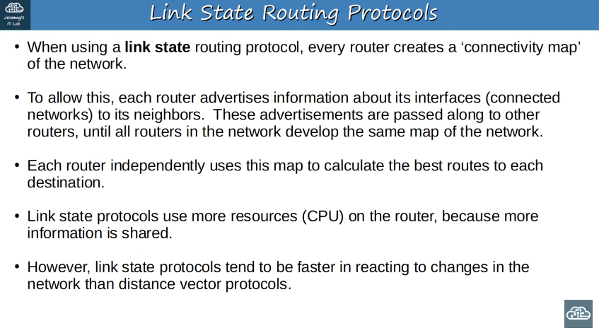
# OSPF
OSPF stands for ‘Open Shortest Path First’. The OSPF protocol uses the ‘shortest path first’ algorithm
Routers store information about the network in LSAs (Link State Advertisements), which are organized in a structure called the LSDB (Link State Database).
- Example: